FEA Projects
SimFirst, an engineering consulting firm, was founded in 2018 to provide quality solutions in the Engineering and CAE fields.
Nuclear Applications
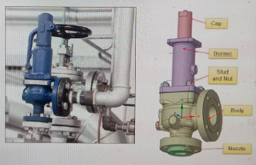
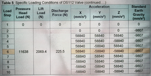
Seismic analysis requested to check the conformance of valve as per ASME BPVC-III Rules for the construction of Nuclear Facilities components Division 1 – Subsection NC Class 2 Components.
ChallengesSeismic analysis, drafting standard format report
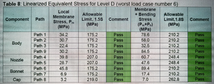
ConclusionsThe spring loaded safety valve DS112 qualifies seismic evaluation requirement as per ASME BPVC III, Division 1-NC
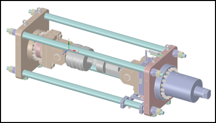
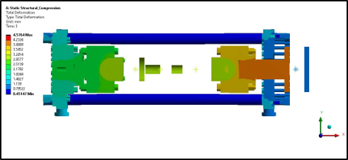
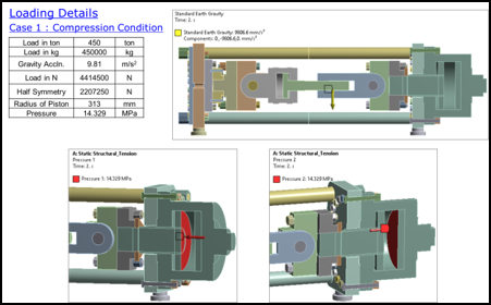
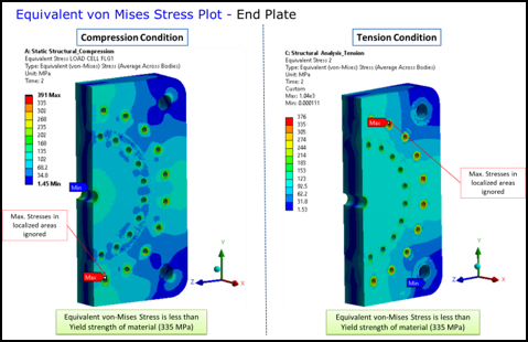
To check and optimize the strength of major parts of Hydraulic Test Bench for tension, compression & buckling condition.
ChallengesIdentifying Loading & Boundary conditions for assembly in neutral position.
Conclusions- For tension & compression loading, the equivalent von-Mises stress for all parts are below yield strength.
- For buckling condition, design load factor from ANSYS (Load Multiplier) is 12.
Defense Applications
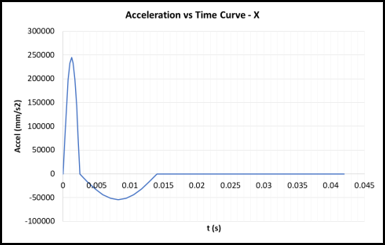
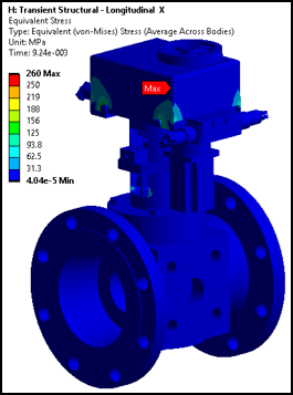
To find out the strength and integrity of pressure regulator valve assembly for shock in all three directions X, Y & Z.
ChallengesShock analysis
ConclusionsShock Analysis of valve in Longitudinal X, Horizontal Y and Vertical Z direction
- All parts have stresses below yield strength.
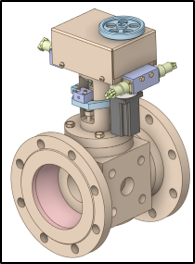

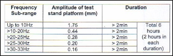
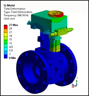
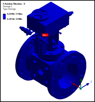
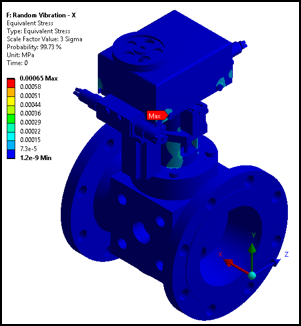
To find out the strength and integrity of pressure regulator valve assembly for Random Vibration in all three directions X, Y & Z.
ChallengesRandom vibration profile
Conclusions- Since total damage in valve for all three directions X, Y & Z for 2 hours is less than 1. Hence the valve assembly is safe for random vibration.
- Random Vibration – X, Y & Z Direction All parts have equivalent stress (3 sigma) less than yield strength.

Oil & Gas Applications
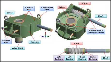
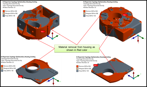
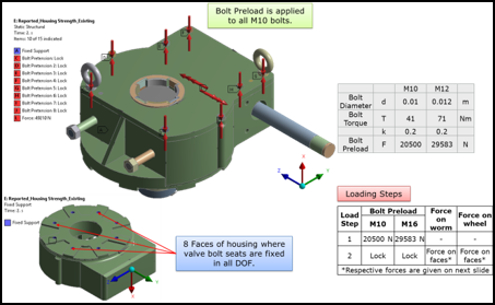
Optimization of Electrical Actuator Worm Gear Housing Assembly for applied torque.
ChallengesSolving actual loading condition & splitting forces on various parts.
ConclusionsShock Analysis of valve in Longitudinal X, Horizontal Y and Vertical Z direction
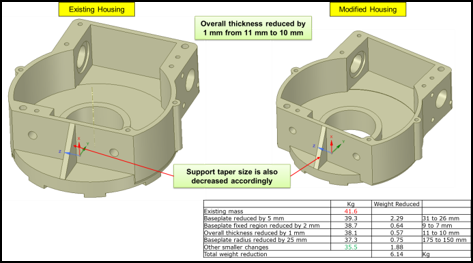
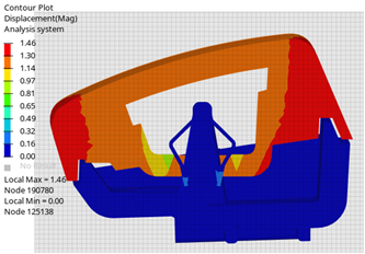
- The total deformation of housing and cover is slightly increased but it is within acceptable range.
- The total weight reduction in existing assembly is 5.88 kg based on stress limits in housing & cover.
Other Projects - Valve Analysis
- 24” ANSI 600 Ball Valve Testing Analysis as per ASME
- Evaluate Body & Adaptor for hydro test as per ASME BPVC.VIII.2-2017 & external axial load & bending moment
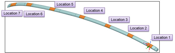
- To identify strain gauging locations on the assembly.
- Safety valve Pressure Integrity Analysis (CRN)
- Stress evaluation of safety valve model 900 as per ASME guidelines for CRN (Canadian Registration Number) certification.
- 6” ANSI 600 Dual Chamber Senior Orifice Fitting ASME Analysis
- Evaluation of orifice fitting as per ASME BPVC.VIII.2-2017 Part 5 at maximum allowable working pressure P (1500 PSI) and working temperature between (-20 to 100F) for Protection Against Plastic Collapse and Protection Against Local Failure.
- Seismic analysis of 30”x30” ANSI 300 Ball Valve as per Euro Code EN 1998-1
To evaluate 30”x30” ANSI 300 Ball Valve assembly as per Euro Code EN 1998-1 for seismic requirement
Automotive
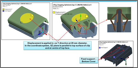
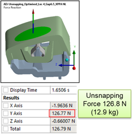
To optimize the snap fit of car roof rail for force requirement of snapping & unsnapping 6.5 kg (max) & 11 kg (min) respectively.
ChallengesShock analysis
Conclusions- The force required for snapping & unsnapping will be approximately 8.2 kg & 12.9 kg.
- For snapping & unsnapping, the equivalent strain in all the components are below break limit.
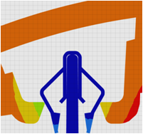
| Location | Total Deformation (mm) | Snapping Force (kg) | Unsnapping Force (kg) |
|---|---|---|---|
| 4 | 1.62 | 8.2 | 12.9 |
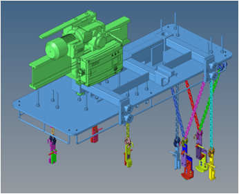
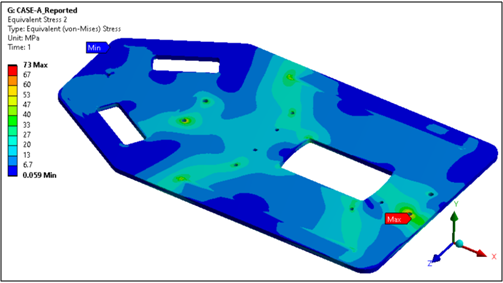
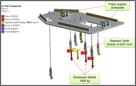
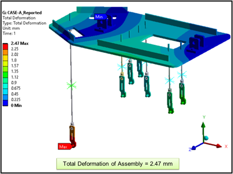
To check the strength of all parts of lift tackle for lifting Jaguar engine.
ChallengesCAD Modeling and mapping with actual model. (Reverse Engineering)
Conclusions- The FOS of Lifter assembly (CASE-A) is almost 1.6 for 1000 kg loading with E250 material.